9 Results
View results:
Sort by:
Question
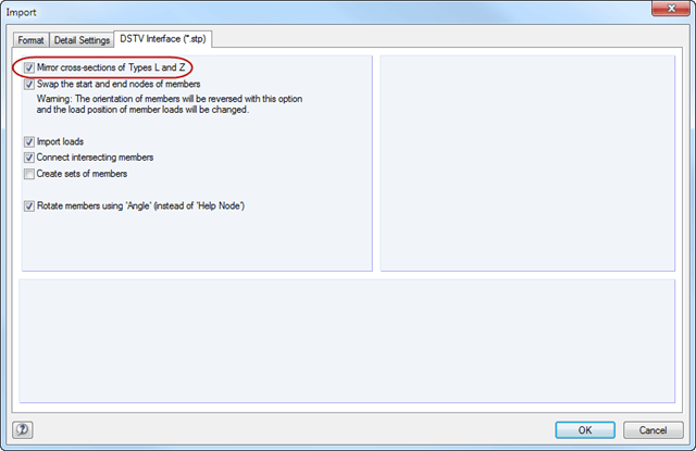
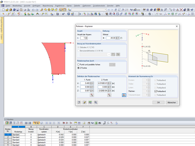
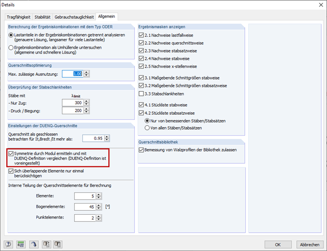
It is not possible to design a SHAPE‑THIN cross-section due to invalid symmetry. What is the cause and how can I fix it?
Question
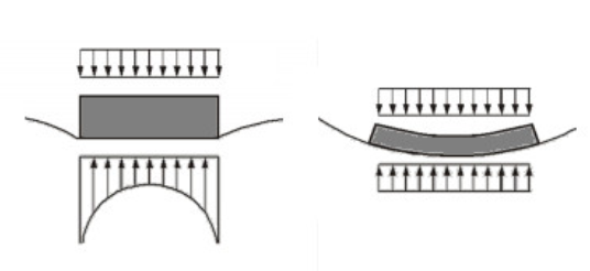
Why do I obtain such high contact stresses at the foundation edges of my floor slab?